Remove the fuse for the air supply system and release the pressure in the system. Remove the rear wheel, brake disc and support the bearing support with a garage jack. Remove the wheel speed pulse sensor.
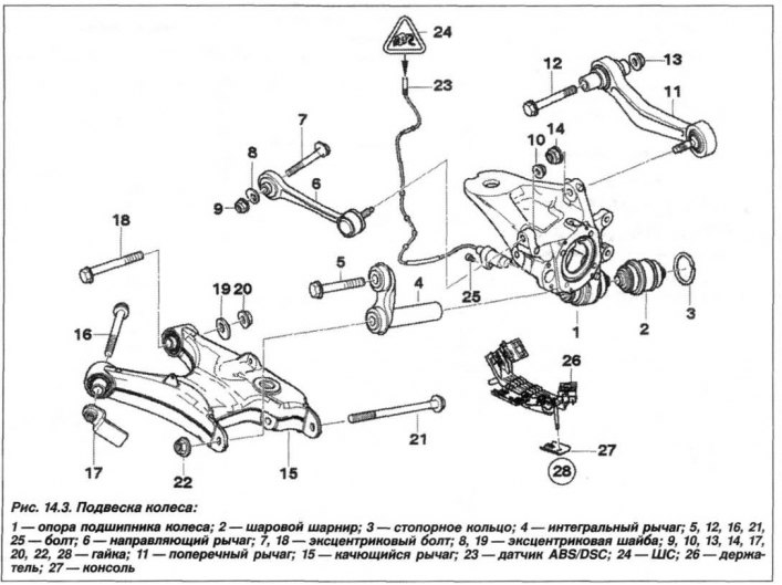
Loosen the nut (14, see fig. 14.3) control arm joint (11) from support (1) bearing, if necessary, hold it against turning by the hexagon of the lever.

open valves (arrows, fig. 14.41) retainer (2) pipelines and disconnect pipelines. Loosen the nut (arrow) and remove the plastic cover (3).

Loosen the nut (13, see fig. 14.3) and remove the bolt (12) control arm mounting (11) to the rear axle beam. Remove the transverse link from the rear axle beam.
Installation of the transverse arm should be carried out in the reverse order, while making sure that the bolt (12) mounted with the head in the direction of travel. Replace self-locking nut (13) tighten it first by hand, and then finally to a torque of 100 Nm (10.0 kgf·m) on a loaded vehicle.
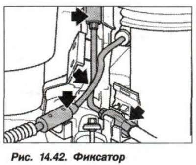
Replace piping retainer and pay attention to piping (arrows, fig. 14.42).

There must be no traces of grease on the hinge pin and in the support hole. self-locking nut (14, see fig. 14.3) replace the hinge and tighten it by hand. Finally tighten the nut on a laden vehicle to 165 Nm (16.5 kgf·m).
On a vehicle with a spring spring, the replacement of the control arm must be carried out in the same way, while it is necessary to disconnect the shock absorber from the rocker arm.
