The generator is driven by the crankshaft using a V-ribbed belt. In this case, the rotor with the excitation winding rotates inside the fixed stator windings.
Through the carbon brushes and slip rings, the excitation current flows through the excitation winding. This creates a magnetic field.
The position of the magnetic field relative to the stator windings is constantly changing as the rotor rotates. In this case, an alternating current appears in the stator windings.
Since the battery can only be charged with direct current, the alternating current is converted into direct current using a rectifier consisting of diodes. The voltage regulator changes the charging current by turning on and off the excitation current in accordance with the state of charge of the battery. At the same time, the regulator keeps the operating voltage constant at about 14 V, regardless of the engine speed.

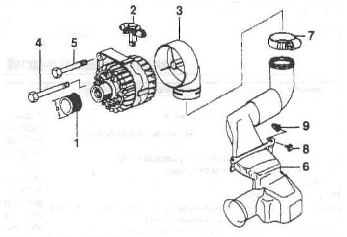
Alternator installation elements
1 - pulley;
2 - voltage regulator;
3 - fitting for air supply;
4 — a bolt with a six-sided head;
5 — a bolt with a six-sided head and a washer;
6 - air duct;
7 - collar;
8 - self-tapping screw;
9 - tin nut.
Precautions when working with an alternator
Do not confuse the wires of the voltage regulator and the generator. Mark the wires with adhesive tape before disconnecting.
Do not disconnect the wires from the battery or from the voltage regulator while the engine is running.
Do not remove the alternator with the battery connected.
When carrying out welding work, be sure to disconnect the battery.
