Some models are equipped with a TDC sensor mounted on the front of the engine. This sensor is designed to work with the BMW test unit and does not apply to the Motronic ignition system.
Speed and position sensors
Examination
1. Locate the two sensor electrical connectors. Gray connector (A) refers to the position sensor, and black (IN) - to the speed sensor.
early models
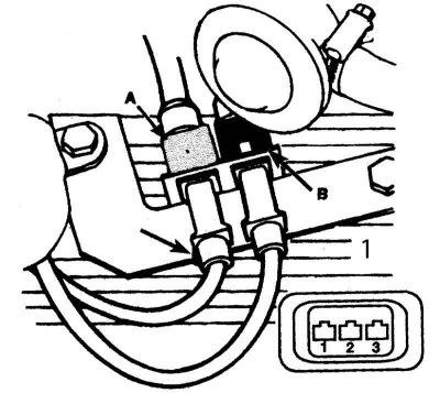
1 - Cylinder head cover
Later models
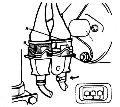
1 - starter
2. On each connector on the sensor side, use an ohmmeter to check the resistance between pin 1 (yellow wire) and pin 2 (black wire). The resistance should be between 860 and 1060 ohms.
3. Also check the resistance between pin 3 and either pin 1 or 2. The resistance should be approximately 1000 ohms.
4. If the reading is incorrect, replace the sensor (And).
Replacement
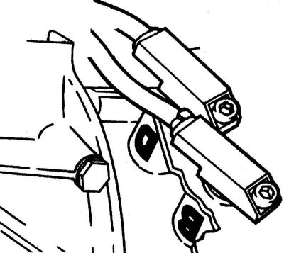
1. Loosen the screw (s) fixing the sensor, if necessary using a bar wrench, and separate the sensor (And) from sockets. Disconnect the wires from the sensors one at a time - make sure that the connectors are not reversed when installing new sensors. On the clutch housing, the place for the position sensor is marked B (gray connector), and under the speed sensor - D (black connector).
When the sensors are removed from the sockets, it is advisable to check the condition of the protrusion on the flywheel. Rotate the engine by hand until the protrusion is in view.
2. Tighten the screw carefully (s) mounting the sensors, being careful not to overtighten the screws.
Pulse sensor (later models)
Examination
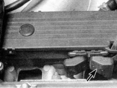
1. Locate the two sensor electrical connectors. Disconnect the connector from the front sensor.
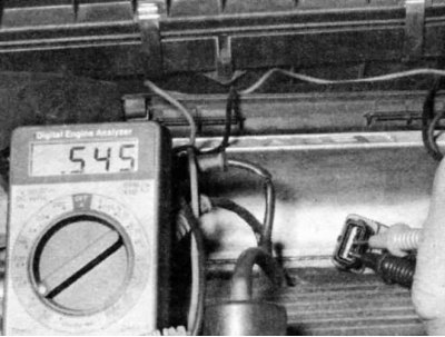
2. Using an ohmmeter, check on each connector on the sensor side the resistance between pin 1 (yellow wire) and pin 2 (black) the wire. The resistance should be between 500 and 600 ohms.
3. If the readings are incorrect, replace the sensor.
Replacement
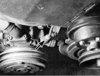
1. Using a 5 mm hexagon wrench, unscrew the pulse sensor mounting bolt. Pulse sensor (shown by arrow) located on the timing belt cover on one side of the pulley (later models). Remove the sensor from the bracket and remove it.
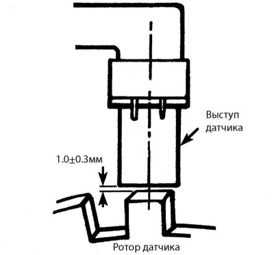
2. When installing a new sensor, use a bronze feeler gauge to maintain the correct distance between the end of the sensor and the rotor. The protrusion of the sensor should be set at a distance of 1.0±0.3 mm from the sensor rotor.
3. Tighten the mounting bolt, being careful not to overtighten.
