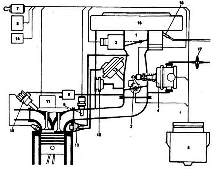
System Diagram «Ecotronic»:
1 - carburetor; 2 - throttle potentiometer of the 1st chamber; 3 - air damper servo; 4 - throttle servo drive of the 1st chamber with an idle switch; 5 - controller; 6 - incoming air temperature sensor; 7 - ignition switch (contact «15»); 8 - main protection relay; 9 - electro-pneumatic ignition timing control valve at idle; 10 - sensor-distributor ignition; 11 - switch (plug «TD ignition signal»); 12 - throttle actuator; 13 - thermostatic valve; 14 - econometer; 15 - air valve of the engine braking system; 16 - air filter; 17 - filter; 18 - fuel supply pipe.

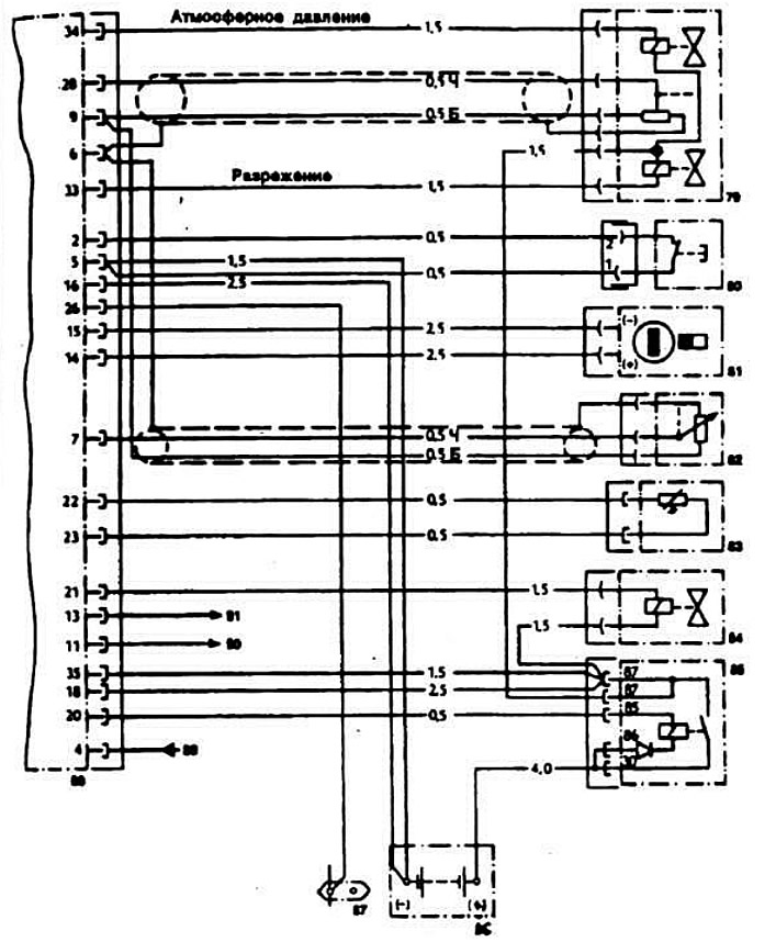
System Diagram «Ecotronic»:
79 - throttle servo of the 1st chamber; 80 - idle switch; 81 - air damper servo; 82 - throttle position potentiometer of the 1st chamber; 83 - temperature sensor of incoming air; 84 - electro-pneumatic valve for regulating the ignition timing; 85 - control relay; 86 - battery; 87 - plug «THAT» (engine speed pulses) switch connector; 88 - controller; 89 - to the plug «15th»; 90 - to the economy labor; 91 - to the point «masses» to take the nominal value of idling. Wire colors: H - black; B is white.

