Note. To install flywheel (faceplates) in place, new bolts and a compound against self-loosening of threaded connections will be required.
Withdrawal
1. Remove the transmission as directed in chapter 7D (mechanical transmission) or in chapter 7B (automatic transmission).
2. On models with a manual transmission, remove the clutch assembly from the flywheel (see chapter 6).
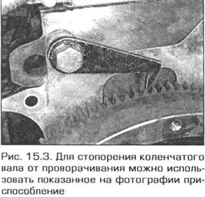
3. To loosen the flywheel mounting bolts (faceplates) the crankshaft must be secured against turning. To do this, you can screw the gear fixture with a bolt, hooking it on the flywheel ring gear. The bolt can be screwed into one of the holes that mount the transmission to the engine (pic. 15.3).

4. Gradually loosen and remove the flywheel mounting bolts (faceplates). Be aware: flywheel (faceplate) mounted on a pin. Remove the flywheel (faceplate) from the shaft.
Attention! The flywheel/faceplate is heavy. Don't drop on your foot.
5. Remove spacer between transmission and engine (if she is).
Installation
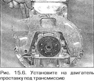
6. Install spacer between engine and transmission (if she stood there before dismantling) on engine pins (pic. 15.6).

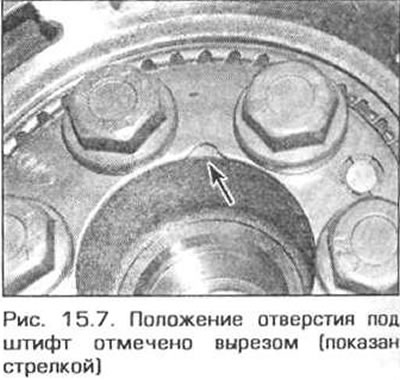
7. Put on the flywheel (faceplate) on the crankshaft shank. so that the shaft pin fits into the hole in the flywheel. On thickened flywheel, the position of the pin hole is marked with one or two cutouts (pic. 15.7).

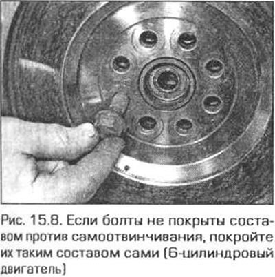
8. On a 6-cylinder engine, inspect the threads of the new flywheel mounting bolts (faceplates). If the threads of the bolts are not coated with anti-self-loosening compound. cover them with such a composition yourself, then screw in the bolts (pic. 15.8). On a 4-cylinder engine, the bolts do not need to be coated with this compound.

9. Gradually tighten the bolts in a diagonal sequence to the required torque. Hold the crankshaft from turning. turning over the tool used to remove the bolts.
10. Install the clutch assembly on the flywheel (see chapter 6).
11. Install the transmission to the engine as indicated in chapter 7A (mechanical transmission) or in chapter 7B (automatic transmission).
