Disassembly
Install the washed and cleaned engine on a turntable for disassembly.
Remove the intake and exhaust manifolds.
Remove the ignition distributor and fuel pump.
Remove the TDC sensor, alternator drive belt, pulley and alternator.
Remove the cylinder head as above.
Remove the oil pan.
Remove the vibration damper from the hub.
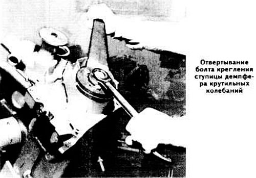
Block the crankshaft from turning with a wrench 11 2 150.
Loosen the bolt of the vibration damper hub and press it, for example, using a Kukko puller 00 7 501 with grub screws 11 2 132.
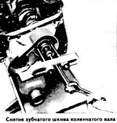
Remove the camshaft drive belt and press the crankshaft sprocket, e.g. with Kukko puller 00 7 501 with grub screws 11 2 131.
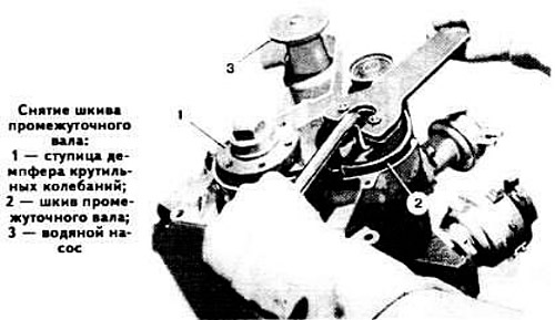
Block the intermediate shaft pulley with a key 11 2 190, unscrew its fastening bolt and remove the washer.
Remove the intermediate shaft pulley.
Remove the front cylinder block cover.
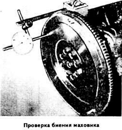
Disconnect the clutch cover from the flywheel.
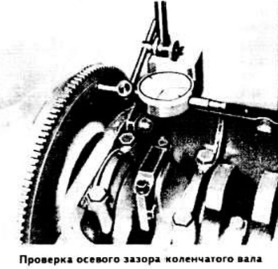
Measure the axial free play of the crankshaft with an indicator.
Remove the flywheel, then remove the crankshaft rear oil seal holder.
Check the markings on the connecting rod caps (caps are counted from the camshaft drive side). Loosen the nuts of the connecting rod bolts, remove the connecting rod caps and the lower connecting rod bearing shells and put them in order.
Mark the main bearing caps, remove them together with the lower shells and put them in order.
Remove the crankshaft from the bearing seats.
Press out the needle bearing with puller 11 2 010.
Assembly
New crankshafts are factory marked with red or blue paint on the side surfaces of the counterweights. Crankshafts with ground necks are marked with paint on the main and connecting rod journals: one color line corresponds to the 1st repair size, two color lines indicate the 2nd repair size.
Warning. The crankshaft has been specially machined and can only be ground in the factory.
Thoroughly clean the working surfaces of the crankshaft bearing shells and main journals. Lay a piece of PGI type plastic gauge wire on the neck surface. Install the main bearing cap on the neck and tighten the mounting bolts, preventing the crankshaft from turning. Remove the cover and, using the scale printed on the package, determine the size of the gap between the main journal and the liner by flattening the wire.
Press the needle bearing into the rear flange of the crankshaft with a mandrel, directing the inscription on the bearing towards the flywheel and maintaining the pressing depth, which should be 5 mm.
Install the lower main bearing shells and place the crankshaft into the main bearings.
Install the main bearing caps by aligning the grooves on the bearing shells.
Insert the pistons with connecting rods into the cylinders. Replace the connecting rod bolts every time the engine is disassembled.
Install the crankshaft rear oil seal holder.
Install the flywheel. Check the crankshaft end play and adjust if necessary by replacing the 6th main bearing shouldered bushings.
Install the oil pump.
Apply sealant such as Atmosit or Curil K 2 to the cylinder block at the location of the dowel pins and to the corresponding surfaces of the oil pan.
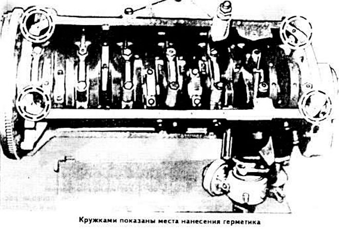
Install the oil pan, then replace the cylinder head.
Install the clutch cover.
